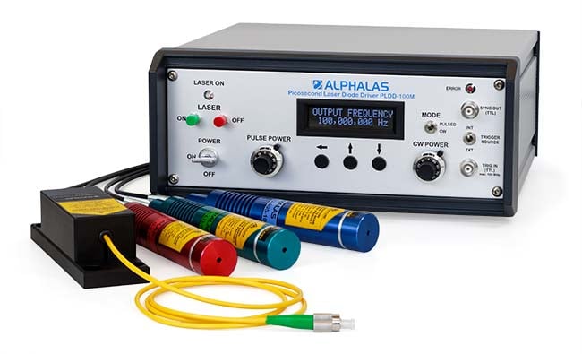
Pulse Laser Diode Drivers For Mac
LaserGRBL is one of the best Windows GCode streamer for DIY Laser Engraver. LaserGRBL is able to load and stream GCode path to arduino, as well engrave images, pictures and logo with internal conversion tool. Unlike other GUI, LaserGRBL it is specifically developed for use with hobbist laser cutter and engraver. In order to use all the features your engraver must supports power modulation through S command.
With image engraving (raster to gcode convertion) LaserGRBL could be a good free and easy alternative to picengrave, benbox, T2laser for who don’t need more then a simple and effective tool. I have written it to use with, and I like to share it with everyone who needs.
LaserGRBL is compatible with. Unlike professional laser machines, which are used for cutting the challenging materials such as metals, a DIY Laser Engraver use a low to medium power laser that can engrave or cut only thin materials like leather, plywood, acrylic, cardboard. Usually this low power machine are build by DIY (do it yourself) enthusiast, but some cheap kits (100-200$) can be bought in ebay and assembled by everyone. Professional machine are bundled with their own software. A DIY machine usually does not have software, or has a very simple one. LaserGRBL is intended to give some professional functions to amateur user. Wanna build your own laser engraver?
Basically there are 4 elements talking between them. Personal computer with or. board with. Elettronics (power supply, laser diode, stepper motor & motor driver). Hardware (rails, linear bearing) Personal computer talk to Arduino board via USB in a language called G0 X10 Y10 (Fast move to position X10, Y10) M3 (Turn on Laser) G1 X20 Y10 (Linear move to X20, Y10) is the common name for the most widely used programming language. Basic command set include G0 (rapid positioning) G1 (linear movement) G2 and G3 (clockwise and counter-clockwise arcs). Arduino UNO board with translate this commands to stepper motor pulses, direction control, laser power modulation.
Transform low level TTL signal from Arduino, to high-power signals for stepper motor. Wanna build your own laser engraver?

If you’ve played around with laser diodes that you’ve scavenged from old equipment, you know that it can be a hit-or-miss proposition. (And if you haven’t, what are you waiting for?) Besides the real risk of killing the diode on extraction by either overheating it or zapping it with static electricity, there’s always the question of how much current to put into the thing. DeepSOIC — for a DVD-burner laser that he’s got. His apparatus is both low-tech and absolutely brilliant, and it looks like he’s getting good data. So let’s have a peek. Laser Detector on 3D Printer Scrap First up is the detector, which is nothing more than a photodiode, 100k ohm load resistor, and a big capacitor for a power supply.
We’d use a coin-cell battery, but given how low the discharge currents are, the cap makes a great rechargeable alternative. The output of the photo diode goes straight into the scope probe. He then points the photodiode at the laser spot (on a keyboard?) and pulses the laser by charging up a capacitor and discharging it through the laser and a resistor to limit total current. The instantaneous current through the laser diode is also measured on the scope. Plotting both the current drawn and the measured brightness from the photodiode gives him an L/I curve — “lumens” versus current. Look on the curve for where it stops being a straight line, slightly before the wiggles set in.

That’s about the maximum continuous operating current. It’s good practice to de-rate that to 90% just to be on the safe side. Here it looks like the maximum current is 280 mA, so you probably shouldn’t run above 250 mA for a long time. If the diode’s body gets hot, heatsink it. If you want to know everything about lasers in general, and diode lasers in particular, you can’t beat. We love DeepSOIC’s testing rig, though, and would love to see the schematic of his test driver.
We’ve used “” for years, and we love it, but a pulsed laser tester would be a cool addition to the lab. What to do with your junk DVD-ROM laser? Use the other leftover parts to? But we don’t need to tell you what to do with lasers. Just don’t look into the beam with your remaining good eye! Posted in Tagged, Post navigation.

I tried driving a laser from a DVD once, and have a question. It was a red laser. I removed all lenses in front of the diode, but left it in the mount for some heatsinking. It was pointed at the ceiling. Then driven with a typical variable voltage/current power supply, set to be current limited at all times. (That’s not ideal, but good enough for a quick experiment with an expendable laser.) I started at zero current, and slowly increased it. Soon I saw a dim, 8 inch wide spot on the ceiling, which was about 5 feet away.
It was not uniform, but had a pattern of tiny “ripples”. As I increased the current, the spot got brighter, and the pattern remained constant. When I reached some current point (I forget exactly what, may have been around 150mA) and the spot was quite bright, I noticed the ripple pattern started to change slightly. A few more mA made the change become more dramatic. If I decreased it past that point, the pattern instantly returned to “normal”. I assumed this change meant I was slightly exceeding the current limit of the diode, and didn’t try pushing it much further than that point.
I’ve since read somewhere that a diode laser requires a minimum “threshold current” to actually lase, and below that acts more like a LED. However, I haven’t been able to find anything suggesting what a typical threshold might be, as a percent of max current rating. So now I wonder, was I actually driving it as a LED all that time, and the pattern change was because it was on the verge of lasing? Or was the pattern change due to overcurrent as I originally assumed?
I use simpler method. Connect laser diode to 5 V supply and 470 Ohm resistor. No lasing – go lower with resistance, to 390 Ohms. No lasing, go lower to 330 Ohms, etc until lasing starts. Typically max.
Current is about 50% greater than minimum lasing current, so my final resistor will be about 2/3 (67%) of the value required to start lasing. Also I found that constant current is not required with my described setup: all my laser diodes are fine so far. I have only tried 5 mW though. Of course.if datasheet is available use that.
When the temp of the laserdiode rises, the output at the same current falls. If the temp gets too high the laserdiode dies. Therefore most LDs have a photodiode built in to monitor the output. So you can build a circuit that lowers the current, when the output falls, if you want to drive the LD at its limit. You can also use the built in photodiode to make your measurement. As better the cooling, as higher you can drive the LD, some people use peltier cooling for LDs to get higher output.But if you drive the LD over its maximum limit, even for a very short time, it is dead.
Mostly because the end mirrors gets damaged. Lumen (lm) is a photometric unit and means how a human perceives the power of light output. This is wavelength-dependent and not very useful for technical applications. Lumen applies to the total light output and the used photo diode only measures a nondescript cross-section of an unknown beam profile.
Pulse Laser Diode Drivers For Mac Download
This yields only a relative result; if at all useful, relative movement of the measurement assembly must be fixed to incredibly tight tolerances to yield any useful result 3. Instead of measuring the capacitor discharge time, you could just measure the photodiode current directly. All but the very cheapest multimeters have decades (i.e. Orders of magnitude) of input current range available – this is sufficient.
This is how you do it correctly: A) Use a thermopile as a sensor. Any small Peltier-type thermoelectric cooling element will do. These are available at various electronics distributors. Part numbers are TEC101703 or APH-031-10-13-S. B) The surface of the TEC should be blackened for uniform spectral absorption.
High Speed Laser Diode Driver
Ordinary black soot will do if no high-power pulsed lasers are measured. You can use a copper plate as a surface heat spreader. C) Calibrate using a known beam or heat source. A SMD resistor soldered on one edge of the heat spreader is sufficient. D) For high power levels with significant temperature rise at the sensor surface, you should do a curve fit to a known first-order model (exponential time function). If you use said SMD resistor, this is no effort at all.
(You can use a linear regression after doing a logarithmic transform or just use the respective feature of a spreadsheet calculation program). (Hit “Report” button on accident) (And thanks to Hubert D for expressing this politely): I was a bit mislead by the title “Sciencing ”. For doing a relative measurement only, using a photo diode/transistor like this is fine.
The “wigglyness” in the output curve is transitions (“hops”) in (longitudinal) lasing modes occuring when the laser significantly heats up. For a laser diode that is supposed to be used in a part of its operating area in which these mode hops do not occur, this might indeed be the easiest way to determine maximum operating current. Using a the electrolytic capacitor as supply for the laser diode, you save yourself the hassle of recording a large number of data points for plotting manually if you do not have access to a proper function generator/component tester. Again, if you want to do a “proper” calibration to factory-default power output, the thermopile is a very simple and useful setup.
